


CIMSS and NOAA/NESDIS/STAR/ASPB Calibration
Projects and Research
The calibration of satellite sensors is an important aspect of their use. Calibration enhances the usefulness of satellite products to observe climate variablity and improves the utility of satellite radiances in NWP. Calibration allows for many quantitative products to be derived from the satellite data.
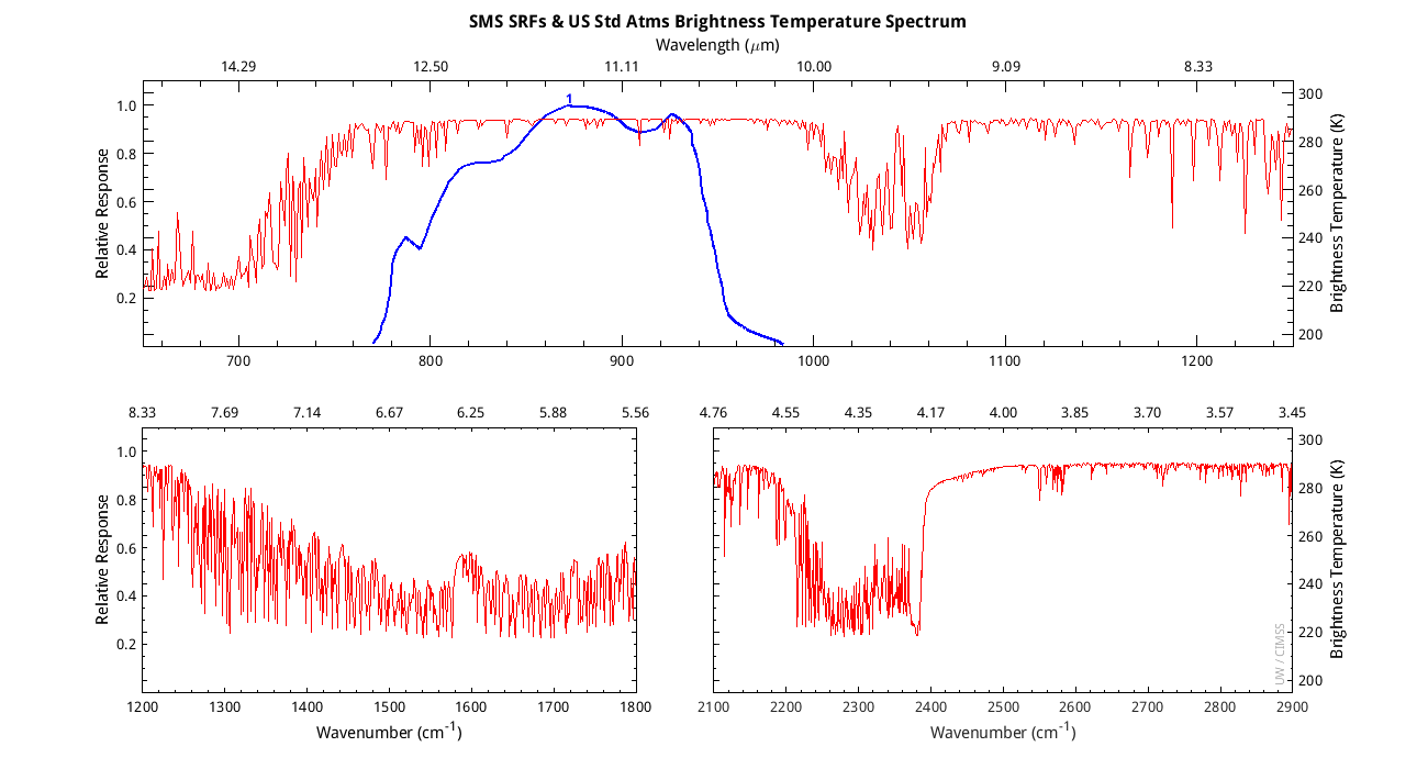
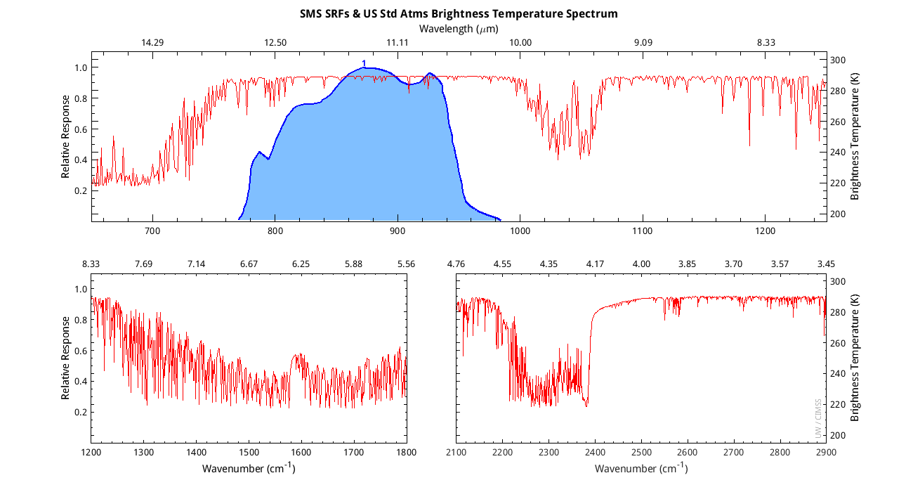
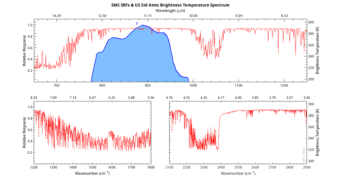
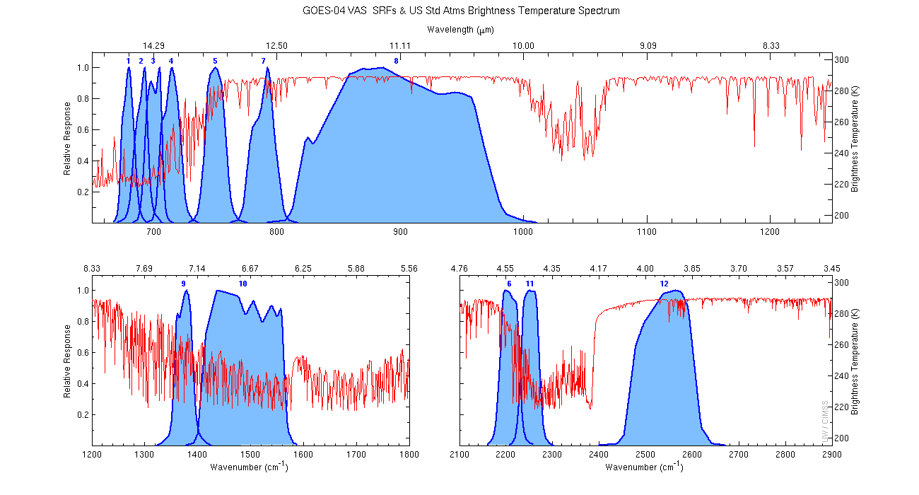
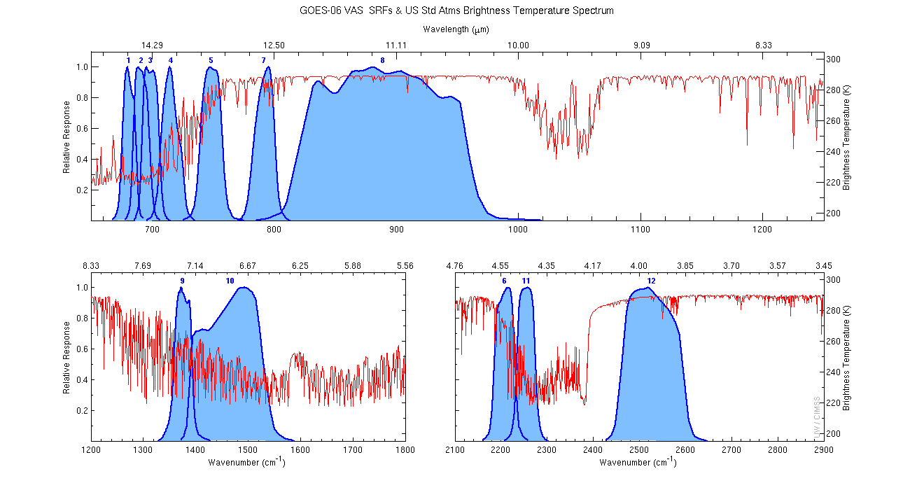
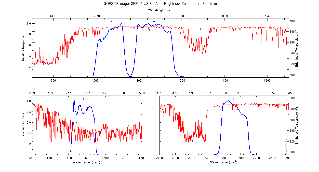
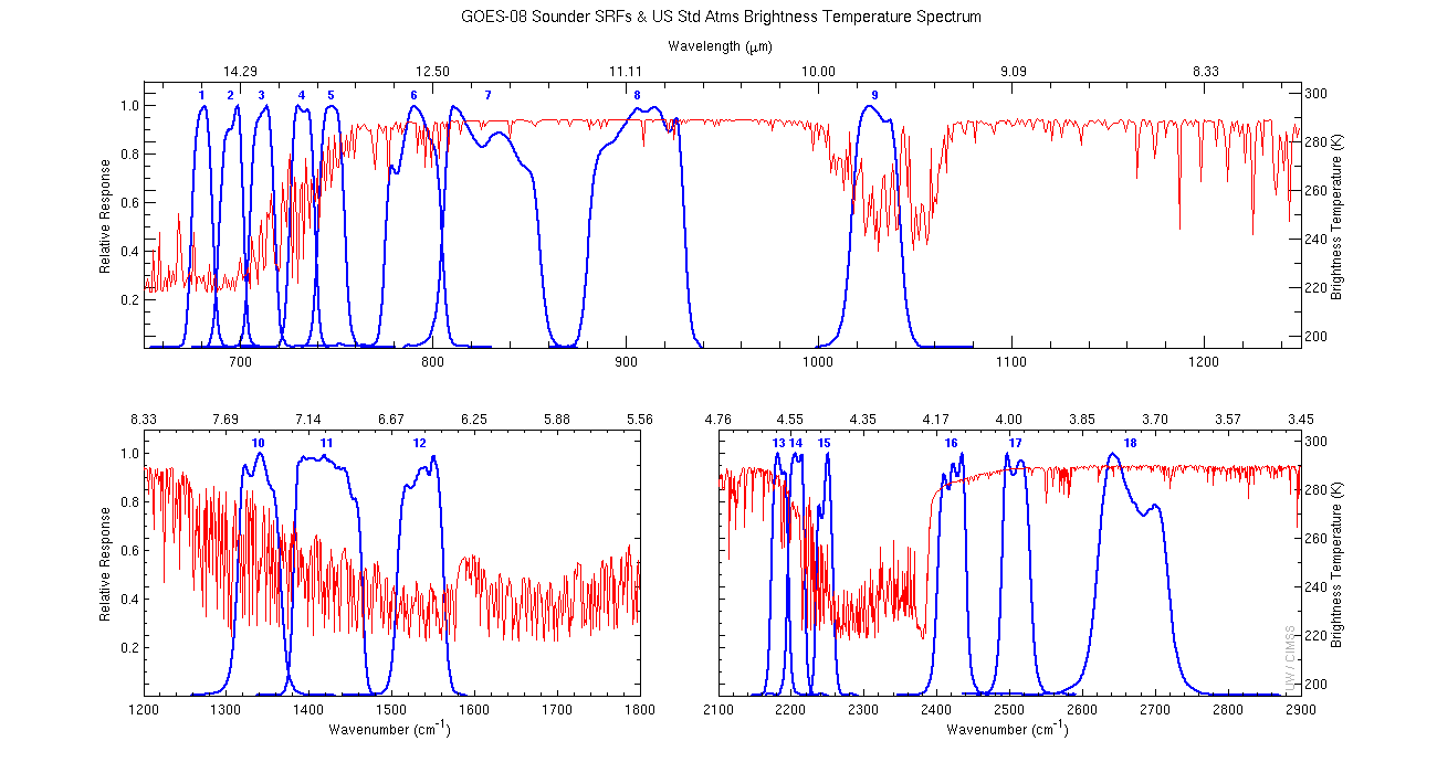
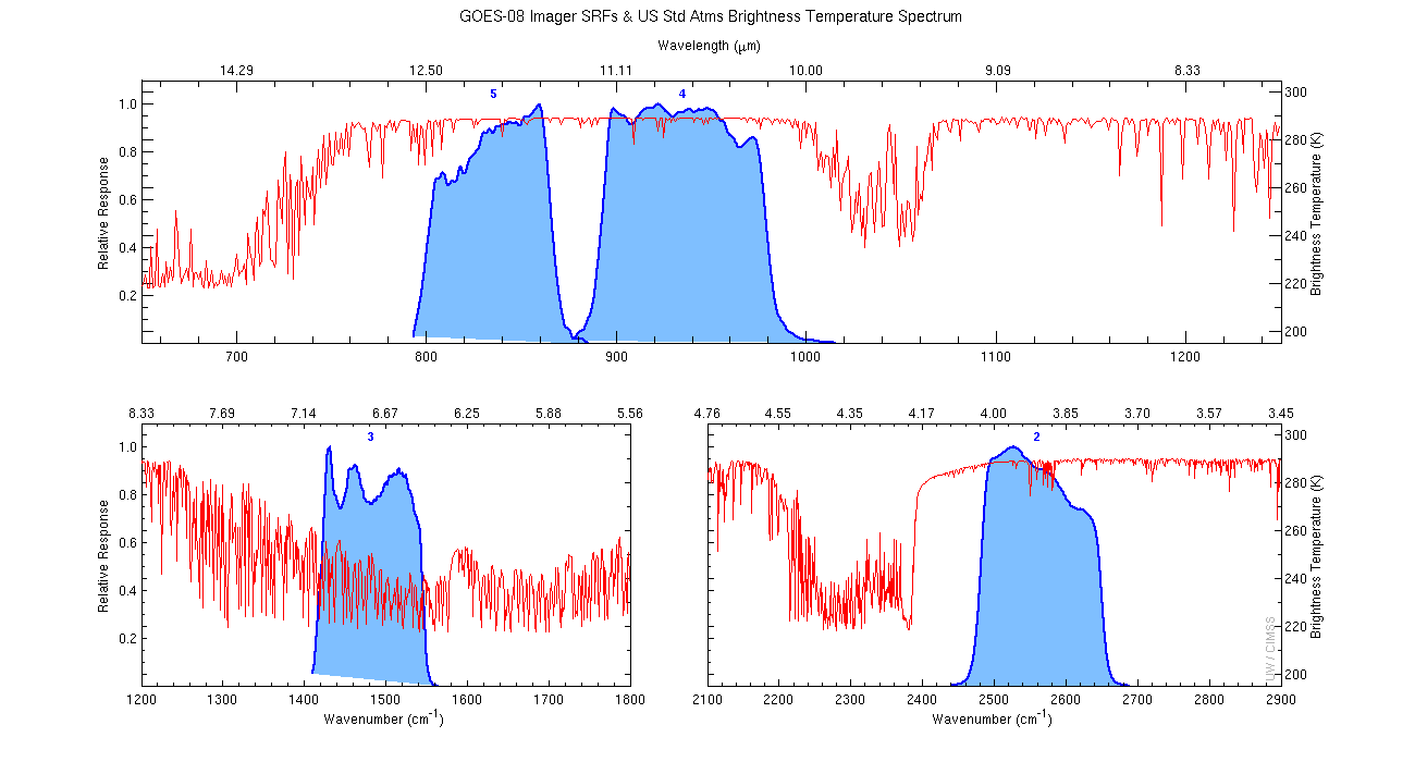
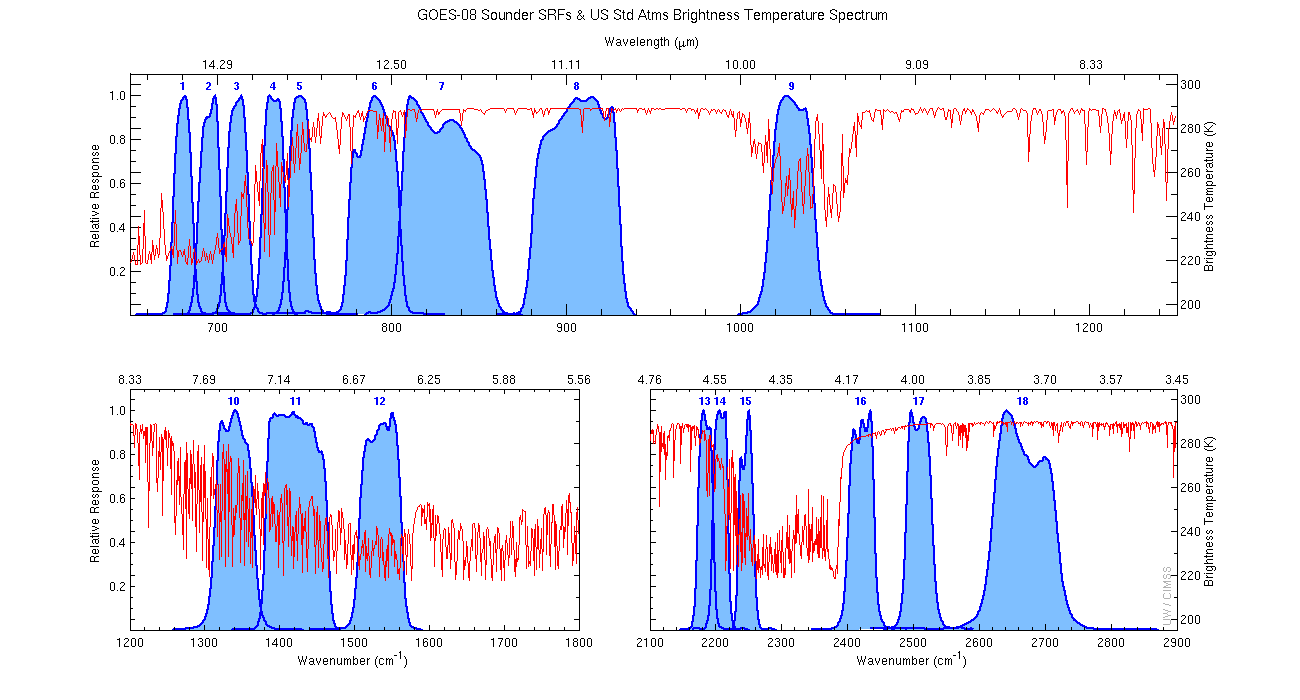
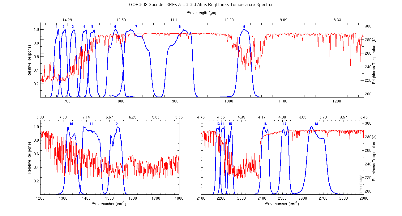
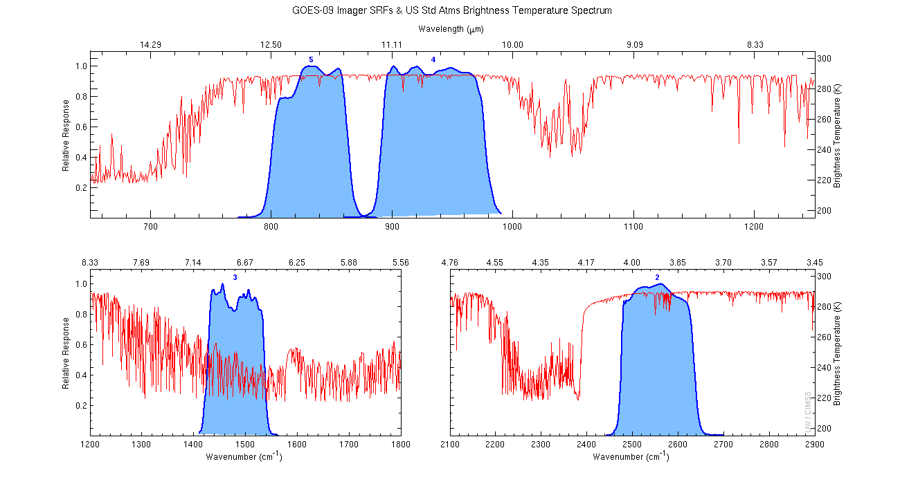
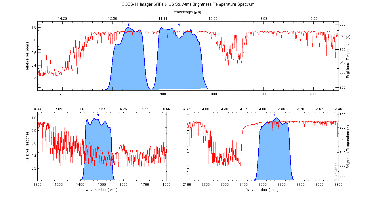
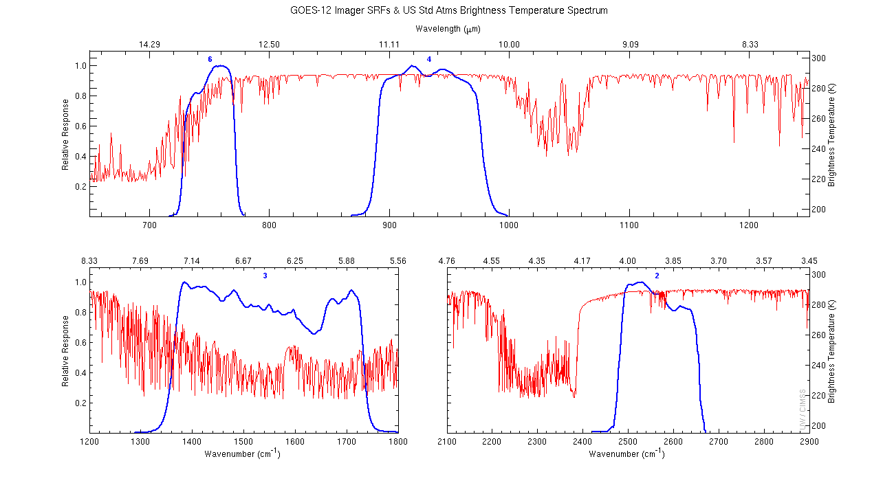
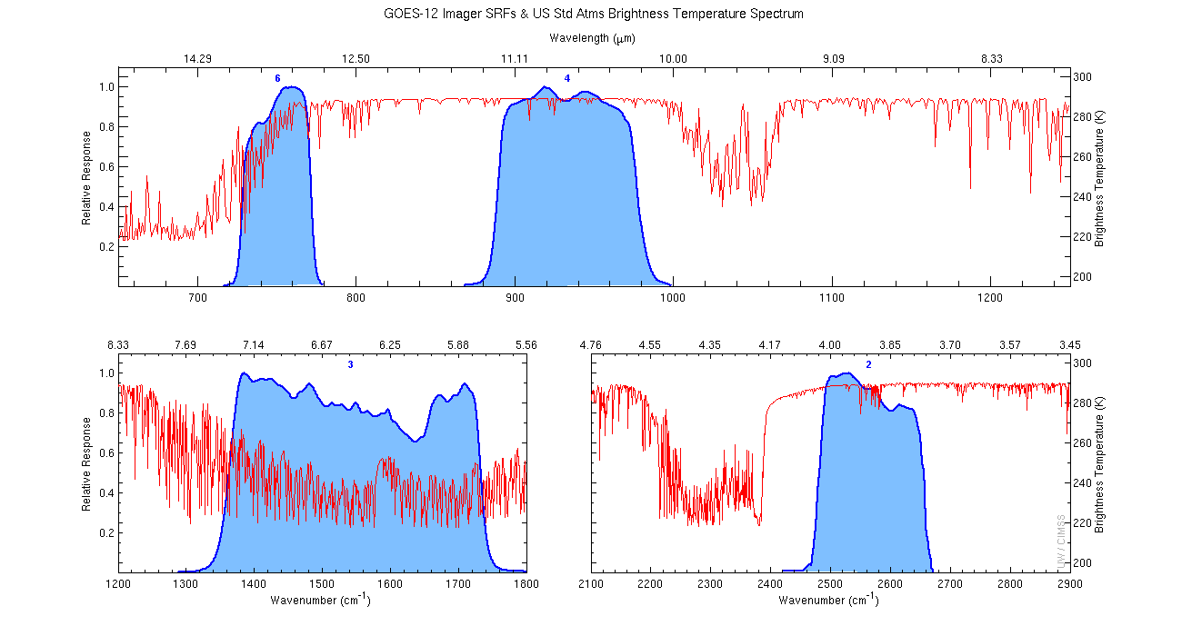
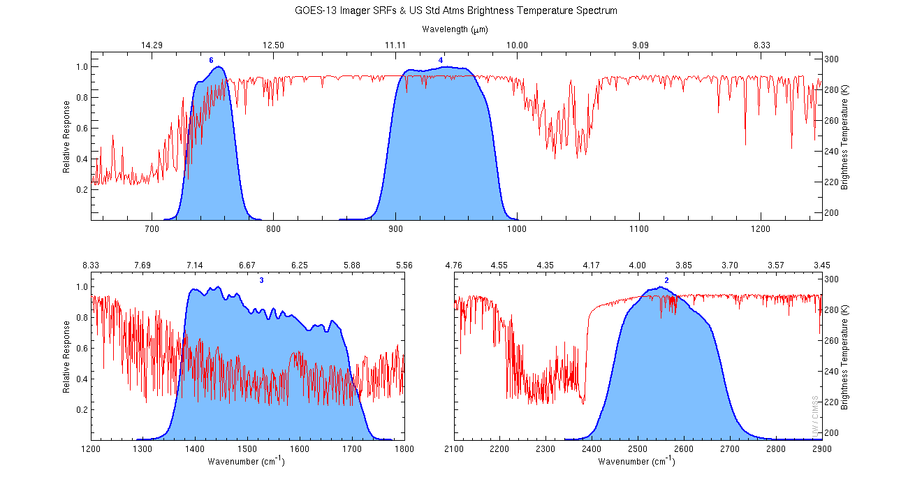
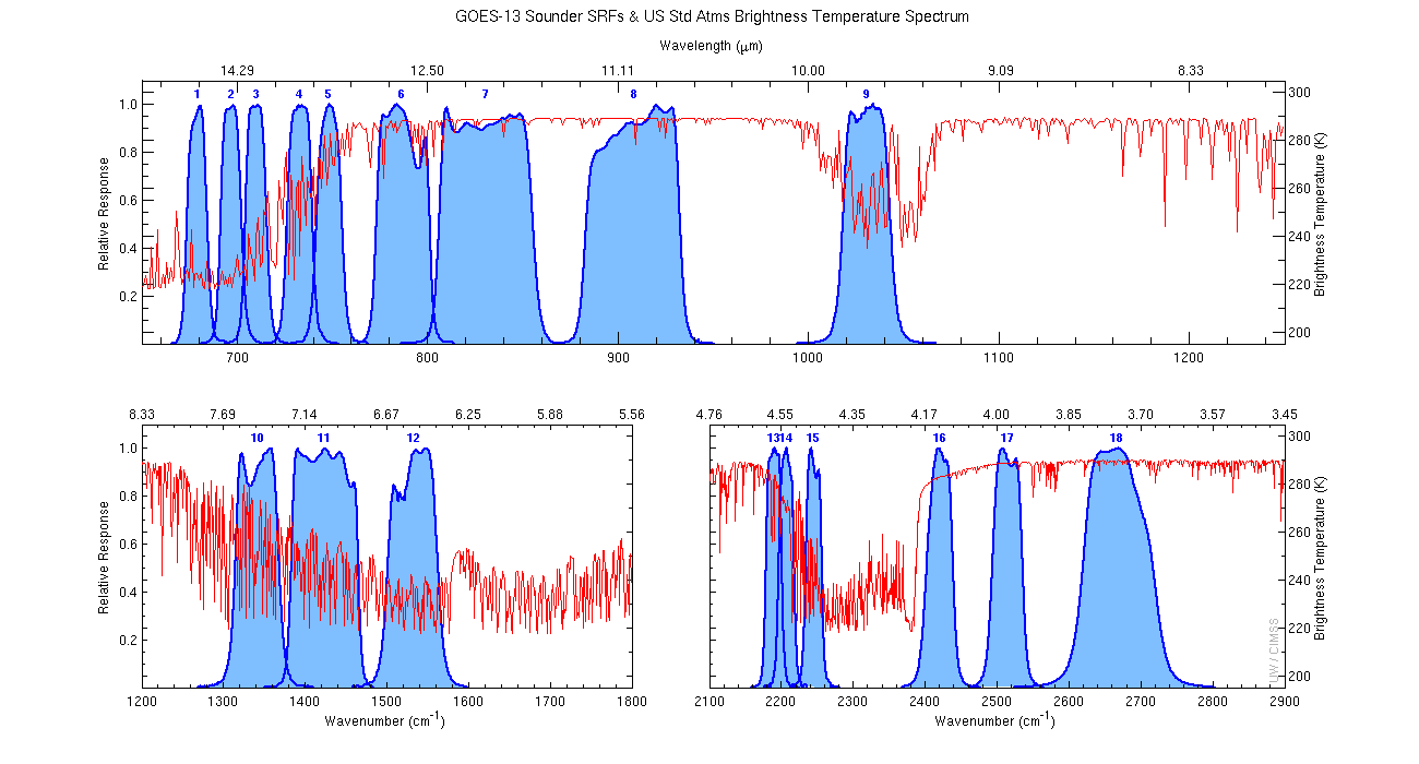
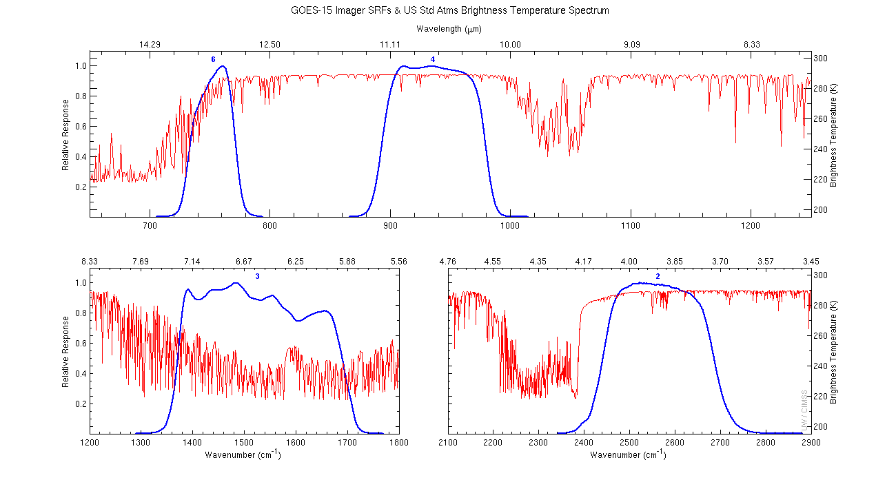
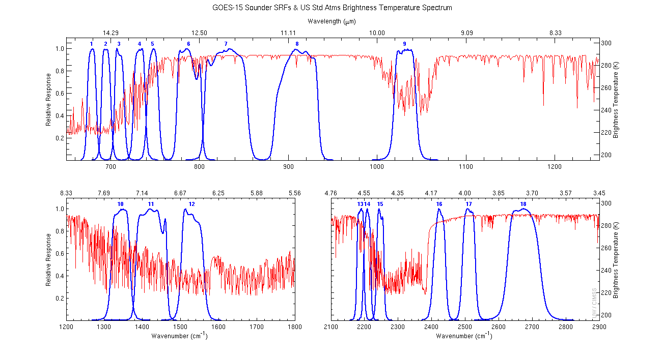
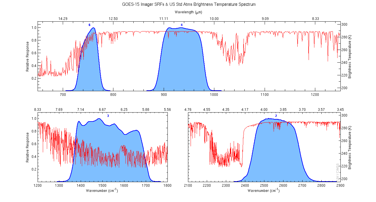
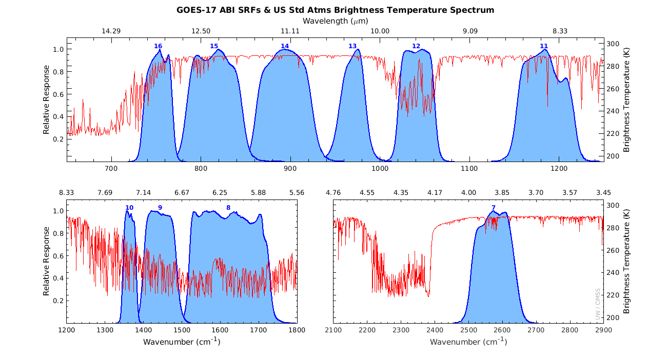
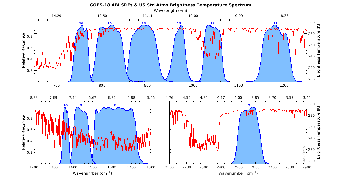
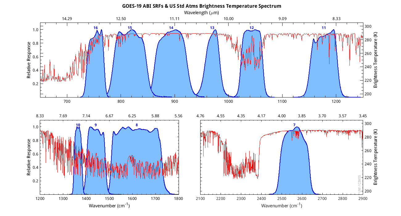
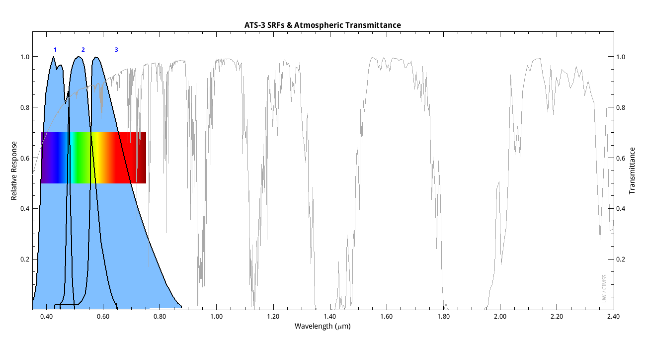
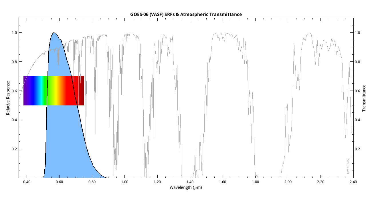
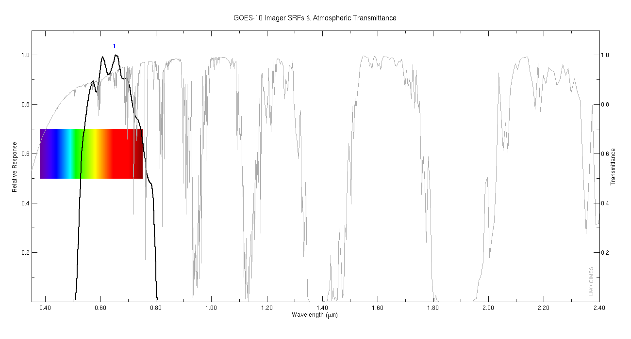
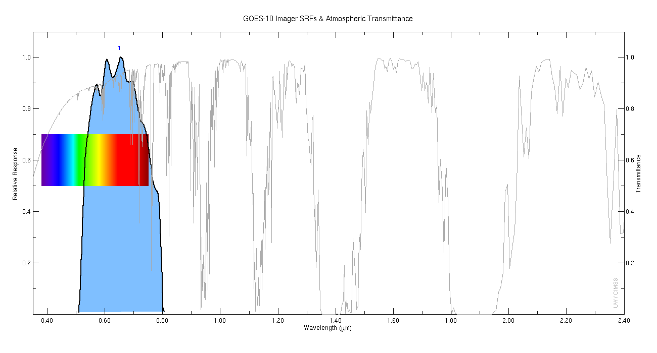
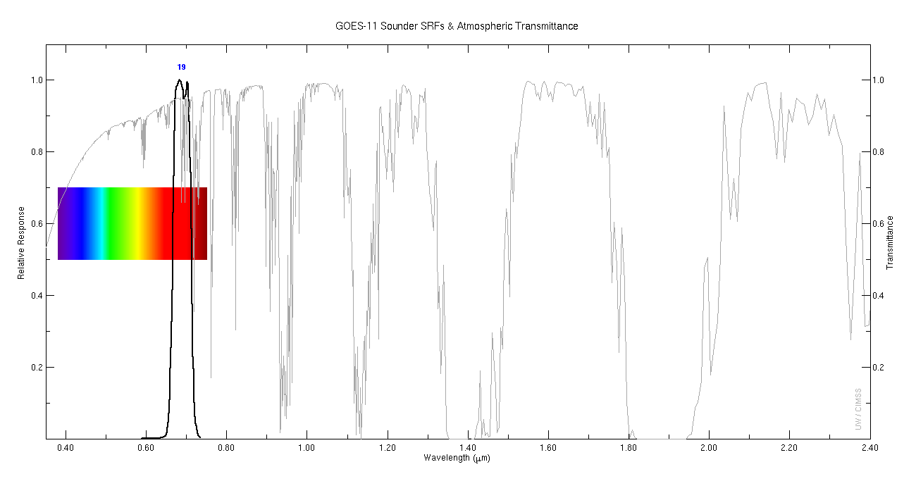
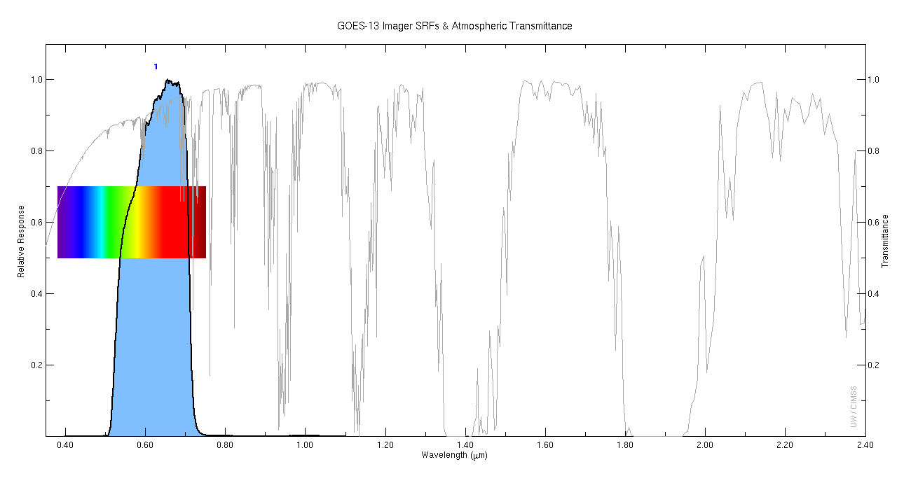
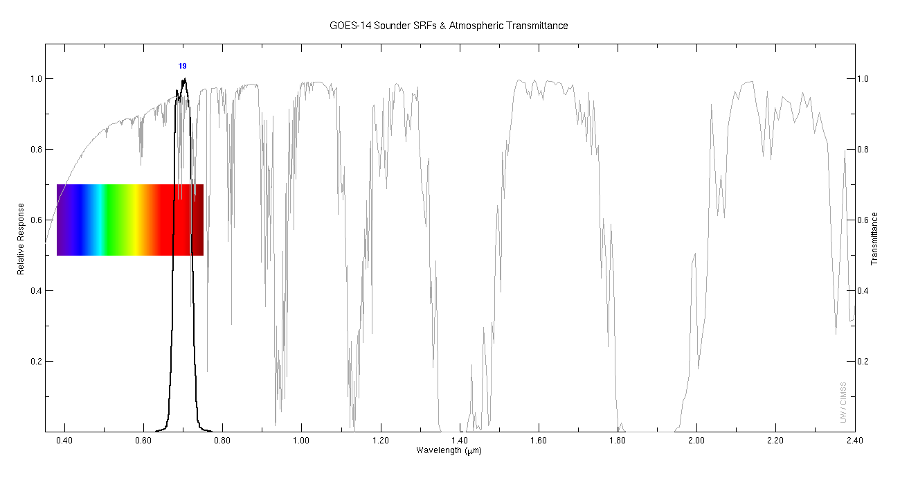
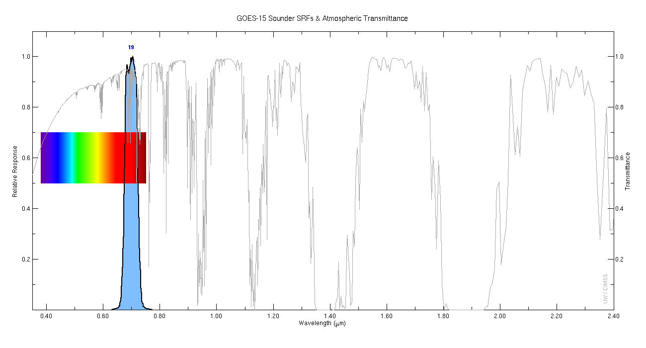
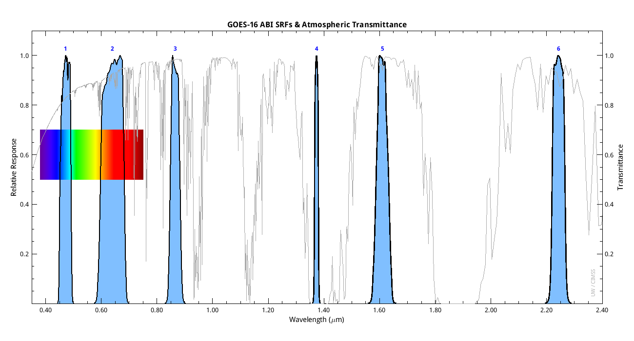
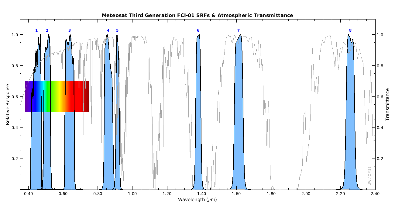
View Plots of Spectral Response Functions. Spectral Response Function (SRF) data are kept for many instruments, including current operational satellites such as GOES-EAST and GOES-WEST and planned instruments not yet in orbit. The plots of Spectral Response Functions for several satellites, along with the U.S. Standard Atmosphere brightness temperature spectrum, can be viewed below.
Updates to Spectral Response Functions & Special Notes. Spectral Response Function (SRF) data are usually not changed after initially released from the vendor, but there are exceptions. We try to note the dates of release when possible.
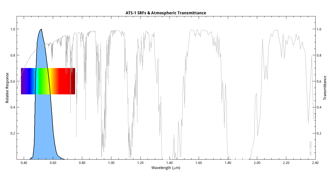
- ATS SRF Data
- The spectral response function data for the ATS-1 Spin-Scan Cloud Camera (SSCC) were found in Table II, page 26 of a technical document from Santa Barbara Research Center titled "Final Report: ATS Spin-Scan Cloud Camera," a copy of which is in the AOSS Library at the University of Wisconsin-Madison.
- The spectral response function data for ATS-3 SSCC were digitized by Tim Schmit (NOAA/NESDIS/STAR) from:
- Suomi, Verner E. and Krauss, R. J.. The spin scan camera system: Geostationary meteorological satellite workhorse for a decade. Optical Engineering, Volume: 17, Issue: 1, 1978, pp.6-13.
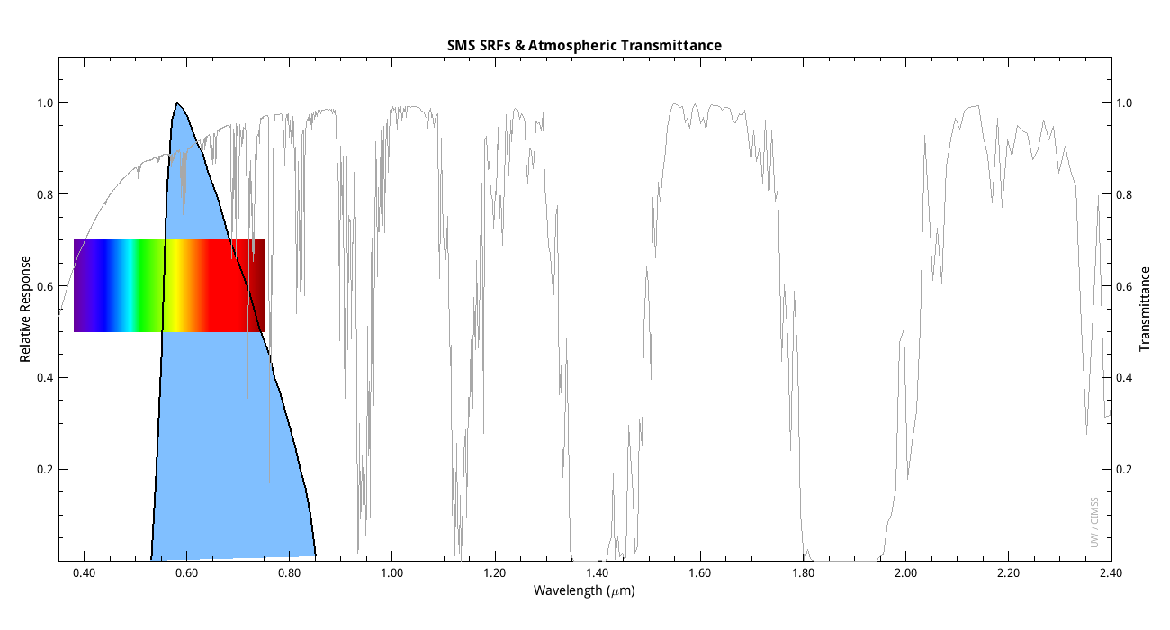
- SMS SRF Data
- The SMS-1 SRFs were digitized, somewhat crudely, from figures 3-103 and 3-104 in this document: https://ntrs.nasa.gov/api/citations/19760066501/downloads/19760066501.pdf on February 29, 2024 by Tim Schmit (NOAA/NESDIS/STAR). The Infrared band had 2 detectors and one was redundant. Based on documentation and e-mail conversations with Paul Menzel and Tom Vonder Haar, it is likely that the thermal channel labeled "1" was the primary detector and "2" was redundant and 2 was never used.
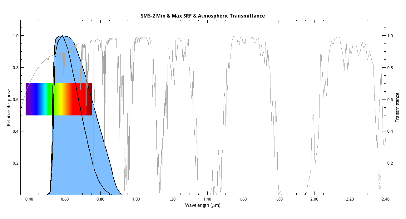
- The SMS-2 and GOES-1 (SMS-C) SRFs were similarly digitized by Tim Schmit in June 2024 from this document: excerpt from the Proceedings of the 43rd Annual American Society of Photogrammetry, which occurred February 27-March 5, 1977 in Washington, DC. Figures 1a and 1b have spectral response functions plotted for the visible bands of VISSR on GOES-1 (SMSC) and SMS-2. We have digitized both the "min" and "max" of the limits presented in those figures.
- As of June 2024, we are unable to find any other SRFs for the SMS series. We only have the one set of IR band SRFs and are still hunting for the rest of the SMS and GOES-1 through -3 series.
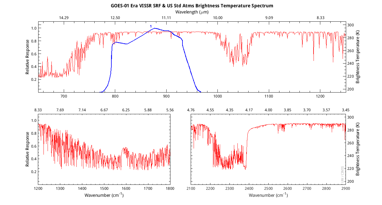
- GOES-1 Era VISSR:
- The Visible Infrared Spin-Scan Radiometer (VISSR) on GOES-1, -2, and -3 (GOES-A, -B, and -C) had 1 infrared band centered near 11.5um. As of June 2024, the only documents found with the SRF in it were technical manuals from the Navy dated 1981 and 1983. It is not clear if it is GOES-01, -02, or -03. Or if the spectral response functions of each instrument were even measured. The documents were found on the Defense Technical Information Center (DTIC) here: https://apps.dtic.mil/sti/tr/pdf/ADA099591.pdf and https://apps.dtic.mil/sti/pdfs/ADA135466.pdf
- GOES-13 Imager Channel 6 (13.3um):
- Version 1: The Original: The original channel 6 SRFs provided by the instrument vendor, ITT, were used during the GOES-13 post-launch tests in 2006 when a warm bias of 2.4 +/-0.6 K in the channel 6 imagery was reported by CIMSS. The warm bias was identified via comparisons with high spectral resolution Atmospheric InfraRed Sounder (AIRS) data on Aqua. The warm bias is consistent with a central-wavelength shift on the order of -4 cm-1 (towards longer wavelengths) with respect to the original channel 6 SRFs. (Used for processing prior to 1 August 2008).
- Version 2: ITT Updated: In response, ITT re-evaluated the pre-launch test data and provided updated SRFs for channel 6 which shifted their effective central wavelengths by approximately -1.2 cm-1. (Used for processing from 1 August 2008 to 26 March 2009).
- Version 3: STAR Updated: NOAA/STAR has evaluated the original warm bias findings, and it has also analyzed a set of observational comparisons with both AIRS and IASI data. This has led to another update to the channel 6 SRFs which shifts the ITT updated SRFs by a further -2.1 cm-1. Thus the STAR-updated SRFs have a total effective shift of approximately -3.3 cm-1 with respect to the original channel 6 SRFs. The STAR-updated SRFs are now the official SRFs for this band and is what we provide here. (Used in processing as of 26 March 2009).
- The STAR updated SRFs appear to remove the original temperature bias of 2.4 K from this band. The following table contains forward model calculations done with the 3 different SRFs (US Standard Atmosphere, Surface Pressure = 1000 hPa, Nadir view).
| SRF Version: | Original SRF | ITT Updated SRF | Star Updated SRF |
| Forward Model BT (K) | 269.6 | 268.8 | 267.2 |
- GOES-14 Imager SRFs Updated to Revision E November 24, 2009:
- Revision A: The Original: The original SRFs provided by the instrument vendor were never used operationally or even during the post-launch science test. All preliminary work (weighting functions, forward model transmittance coefficient file generation, etc) was done using this set of SRFs.
- Revision E: Released November 2009: The instrument vendor, apparently in 2008, released this set of SRFs to the government and NESDIS made them available in late November 2009. All of the post-launch science test data were released with calibration based on this set of SRFs. Code for many users, such as McIDAS, was still based on Revision A SRFs. There was no change to the Sounder SRFs at this time.
Files have filename extension of .SRF but they are simply ascii text files.
| ATS-1 & ATS-3 | ats | ||
| SMS | sms | ||
| SMS-2 | sms2 | ||
| VISSR | vissr | ||
| GOES-01 | goes01 | ||
| GOES-04 VAS | sr4 | ||
| GOES-05 VAS | sr5 | ||
| GOES-06 VAS | sr6 | ||
| GOES-07 VAS | sr7 | ||
| GOES-08 | sr8 | ||
| GOES-09 | sr9 | ||
| GOES-10 | sr10 | ||
| GOES-10new | sr10new | ||
| GOES-10_2002 | sr10_2002 | ||
| GOES-11 | sr11 | ||
| GOES-12 | sr12 | ||
| GOES-12 2002 | sr12_Aug2002 (New sounder SRFs only) | ||
| GOES-13 | sr13 | ||
| GOES-14 (A) | sr14 (Revision A, not used) | ||
| GOES-14 | sr14 (Revision H, STAR Shifted; Operational since August 2011) | ||
| GOES-15 | sr15 (Revision H) | ||
| GOES-R CWG | NESDIS Calibration Working Group (CWG) Site | ||
| GOES-16 ABI | GOES-16 ABI (Prototype Flight Model SRFs released March 2016) | ||
| GOES-17 ABI | GOES-17 ABI (FM2 or Flight Model 2, SRFs released March 2016) | ||
| GOES-17 ABI at 81K | GOES-17 ABI (FM2 or Flight Model 2, SRFs posted 09/04/2019 by CWG) | ||
| GOES-18 ABI | GOES-18 ABI (FM3 or Flight Model 3, SRFs released March 2016) | ||
| GOES-19 ABI | GOES-19 ABI (FM4 or Flight Model 4, SRFs released March 2016) | ||
| VIIRS | Suomi-NPP VIIRS (Government Best, circa Oct 2011) | ||
| METEOSAT-08 | MSG-1 | ||
| METEOSAT-09 | MSG-2 | ||
| METEOSAT-10 | MSG-3 | ||
| METEOSAT-11 | MSG-4 | ||
| MTG FCI 01 | MTG-FCI-01 | ||
| MTSAT-1R | MTSAT-1R links to JMA's webpage | ||
| MTSAT-2 | MTSAT-2 | ||
| AHI-08 | AHI on Himawari-08, version 2 SRFs released Sep 2013 | ||
| AHI-09 | AHI on Himawari-09, SRFs released Oct 2013 | ||
| COMS-1 | COMS-1 |
Central Wavelengths, Wavenumbers, and Bandwidths. The GOES Imagers have similar central wavelengths and bandwidths, however they are slightly different. On GOES-12 (thru GOES-15) the 12 micron channel was replaced with a 13 micron channel (which we refer to as Channel 6). The data in this table were calculated from the Spectral Response Function data (see above). The bandwidth is actually the Full Width at Half Max (the point at which the SRF passes the 50% response mark). Central wavelength is calculated based on this bandwidth by dividing the integral of the response times the wavelength (with respect to wavelength) by the integral of the response (with respect to wavelength). For a spectral response function, such as those we use here, which can be described as a discrete series, the formula can be simplified to the sum of the response times the wavelength divided by the sum of the response.
- GOES-08 Imager GOES-08 Sounder
- GOES-09 Imager GOES-09 Sounder
- GOES-10 Imager GOES-10 Sounder
- GOES-11 Imager GOES-11 Sounder
- GOES-12 Imager GOES-12 Sounder
- GOES-13 Imager GOES-13 Sounder
- GOES-14 Imager GOES-14 Sounder
- GOES-15 Imager GOES-15 Sounder
- Note: The files for GOES-08 through GOES-15 were updated 24 April 2013 to include all bands (IR and the Visible) on all instruments.
- GOES-16 ABI (PFM)
- Note: This is ABI PFM or Flight Model 1, version 3 SRFs released March 2016, now GOES-16.
- GOES-17 ABI (FM2)
- GOES-18 ABI (FM3)
- GOES-19 ABI (FM4)
- FY-2C
- MTSAT-1R
- MTSAT-2
- AHI-08 - AHI on Himawari-08, version 2 SRFs released Sep 2013
- AHI-09 - AHI on Himawari-09, version 2 SRFs released Sep 2013
- COMS-1
- INSAT-3D
Planck Function Constants
Radiometric Conversions. Planck Function constants are used to make the conversion between radiance and brightness temperature or vice versa.
To convert from radiance (mW/m2/ster/cm-1) to temperature:
temp = [ fk2 / (alog((fk1 / rad) + 1)) - bc1 ] / bc2
To convert from temperature (K) to radiance (mW/m2/ster/cm-1):
rad = fk1 / [ exp (fk2 / (bc1 + (bc2 * temp))) - 1 ]
Download Planck Function Constants. The following files contain the Planck Function Constants for GOES-8 through GOES-15. They contain the constants for each band on both the sounder and imager(detector averages).
- SMS Planck Function Constants
- GOES-01 Era VISSR Planck Function Constants
- GOES-08 Planck Function Constants
- GOES-09 Planck Function Constants
- GOES-10 Planck Function Constants
- GOES-11 Planck Function Constants
- GOES-12 Planck Function Constants - Updated 19 Dec 2002
- GOES-13 Planck Function Constants
- GOES-14 Planck Function Constants - Individual detectors for the Sounder and Imager (Side 1)
- GOES-15 Planck Function Constants - Individual detectors for the Sounder and Imager (Side 1)
- GOES-16 ABI Planck Function Constants - ABI PFM or Flight Model 1, v3 SRFs released Mar 2016
- GOES-17 ABI Planck Function Constants - ABI FM2 or Flight Model 2, SRFs released Mar 2016
- GOES-18 Planck Function Constants - ABI FM3 or Flight Model 3, SRFs released Mar 2016
- GOES-19 Planck Function Constants - ABI FM4 or Flight Model 4, SRFs released Mar 2016
- METEOSAT-08 Planck Function Constants
- METEOSAT-09 Planck Function Constants
- METEOSAT-10 Planck Function Constants
- METEOSAT-11 Planck Function Constants
- MTG FCI-01 Planck Function Constants
- MTSAT-1r Planck Function Constants
- MTSAT-2 Planck Function Constants
- AHI-08 Planck Function Constants - AHI on Himawari-08, version 2 SRFs released Sep 2013
- AHI-09 Planck Function Constants - AHI on Himawari-09, SRFs released Oct 2013
- COMS-1 Planck Function Constants
- INSAT-3D Planck Function Constants
Converting Between Radiance Units
The method for converting between radiance units based on wavelength and wavenumber is provided in this memo:
Converting_AHI_RadianceUnits_24Feb2015.pdf. This memo was based
on a previous memo by Frank Padula and Changyong Cao: ABI Max/Min
Radiance Characterization (pdf).
Here are Band Equivalent Widths (EQW) for the following satellites:
- AHI - AHI on Himawari-8, version 2 SRFs released Sep 2013
- GOES-16 ABI - GOES-16 ABI SRFs released Mar 2016
- GOES-17 ABI - GOES-17 ABI SRFs released Mar 2016
- GOES-18 ABI - GOES-18 ABI SRFs released Mar 2016
- GOES-19 ABI - GOES-19 ABI SRFs released Mar 2016
- MTG FCI-01 - Meteosat Third Generation FCI-01 SRFs
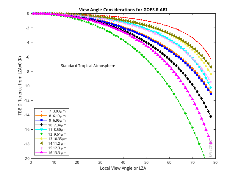
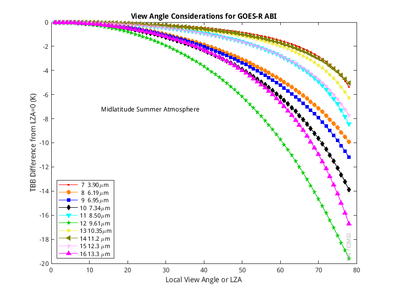
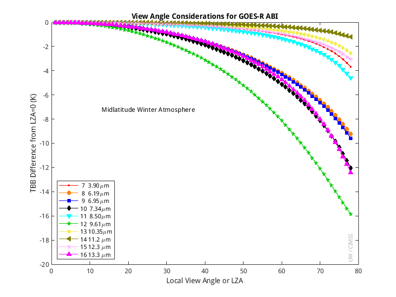
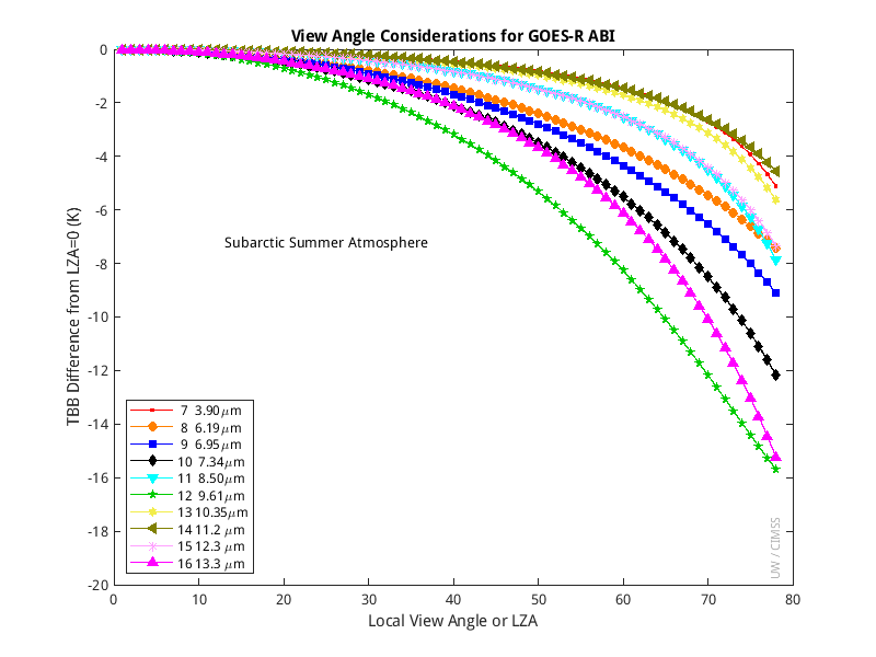
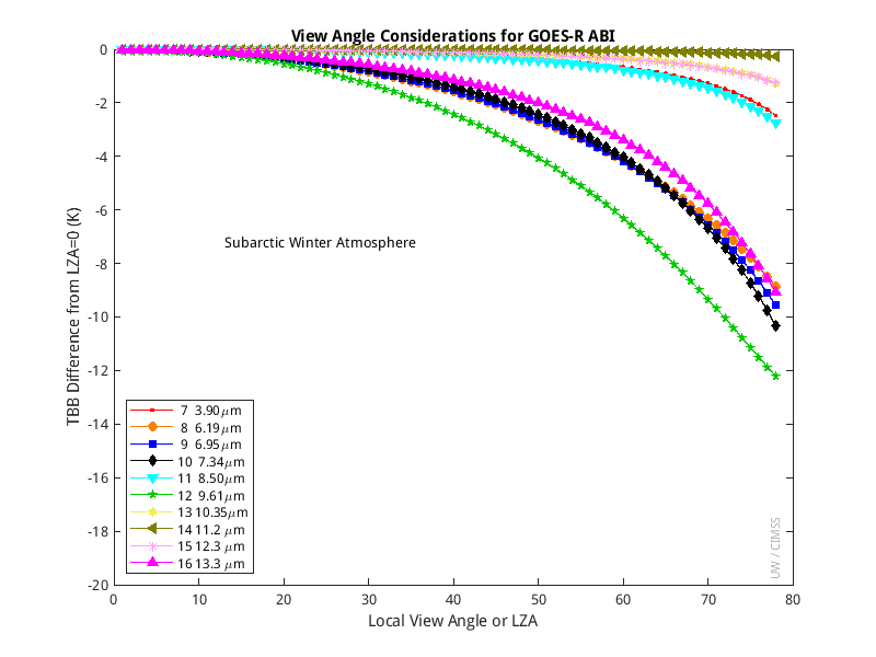
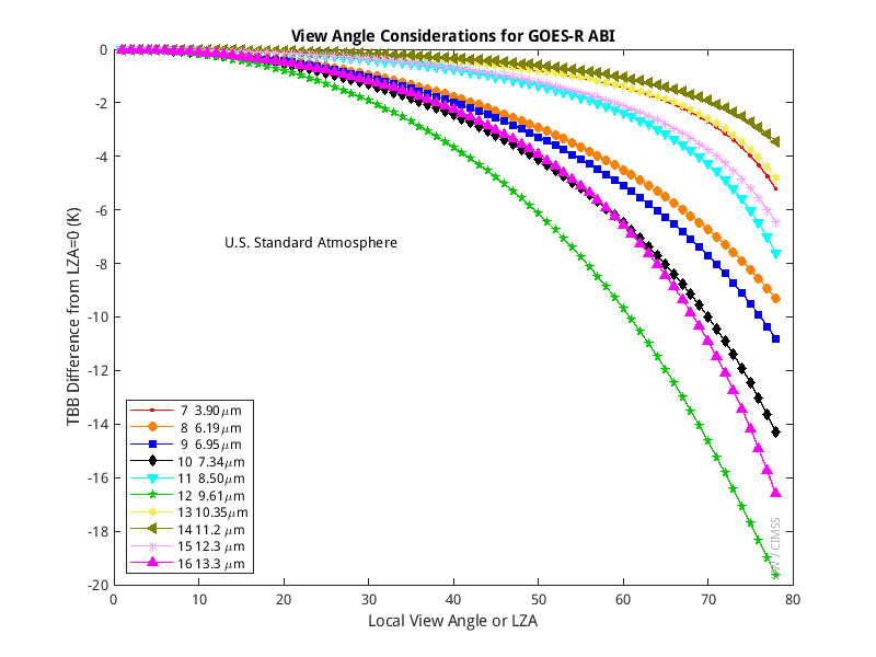
View Angle Considerations
The signal measured by GOES (or any other instrument) is affected by the view angle associated with any given field of view. The magnitude of this effect varies with wavelength and the composition of the atmosphere through which the field of view is seen. These effects can be modeled in a fast forward model calculation. Results for the 10 ABI IR bands are shown below for 6 standard atmospheres.
- Standard Tropical
- Midlatitude Summer Atmosphere
- Midlatitude Winter Atmosphere
- Subarctic Summer Atmosphere
- Subarctic Winter Atmosphere
- U.S. Standard Atmosphere
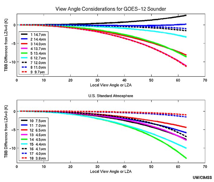
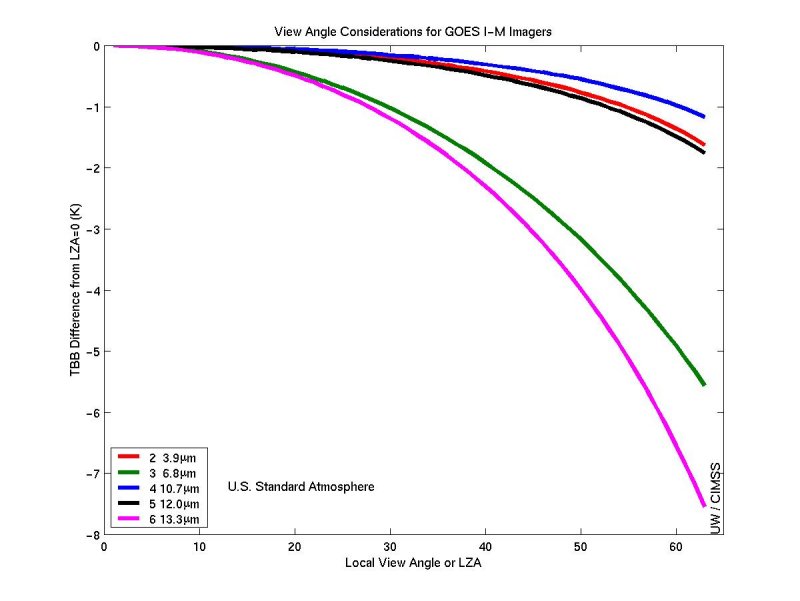
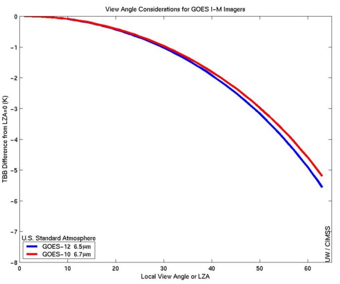
A similar plot for the GOES-12 Sounder and the U.S. Standard Atmosphere can be seen here. The corresponding plot for the GOES-I-M series imager is here. Note that for the imager plot bands 2, 3, 4, and 6 are from GOES-12 and band 5 is from GOES-10. The GOES instruments are spectrally similar for all similar bands with the exception of band 3 on the GOES-I-M imagers (the water vapor channel) where GOES-12 is significantly different spectrally from its predecessors. This plot is still representative of the other GOES imager water vapor bands, though as the view angle increases, the difference between band 3 on GOES-12 and the previous GOES imagers also increases. A plot of GOES-10 and GOES-12 brightness temperature difference due to view angle for band 3 is here.


GOES Post-Launch Science Tests
GOES-10 Check-Out: On March 16 through April 12, 1998 CIMSS performed a science test of GOES-10. Calibration was an important aspect of this project.GOES-11 Check-Out: On May 17 through August 15, 2000 CIMSS performed a science test of GOES-11. Calibration was an important aspect of this project.
GOES-12 Check-Out: On September 23 through October 27, 2001 CIMSS performed a science test of GOES-12. Calibration was an important aspect of this project.
GOES-13 Check-Out: In Decemeber 2006 CIMSS performed a science test of GOES-13. Calibration is an important aspect of this project.
The LEO/GEO intercalibration project is an ongoing research project aimed at comparing the various geostationary (GEO) satellites by using a single polar orbiting (Low Earth Orbiting) satellite.
There are informational pages on each of the GOES instruments that are in operation currently or proposed for future operation. These are mostly for internal use to keep a record of various things we have looked at over the years.
GOES-10 Sounder Banding and Bias ModesNOAA engineers can change the bias mode used in the GOES-10 Sounder calibration process, to help minimize drift in the bias factors (intercepts) between space looks. The bias mode 2 will reduce the 'banding' apparent in some images (ie, channel 12, at times around 10 UTC). An example of this of this can be found on the GOES Sounder FAQ page.
Links
CIMSS GOES-R ABI Imagery Team Page (16-panel imagery, time-difference imagery, imagery statistics, and SUVI displays) NOAA/NESDIS GOES-R Calibration Working Group (CWG) Page on ABI NOAA/NESDIS National Calibration CenterDisclaimer. The products from satellites and instruments shown here are experimental. These have been generated within a research environment and are not intended to be considered operational. Timeliness, availability, and accuracy are sought but not guaranteed.
Return to CIMSS Home Page