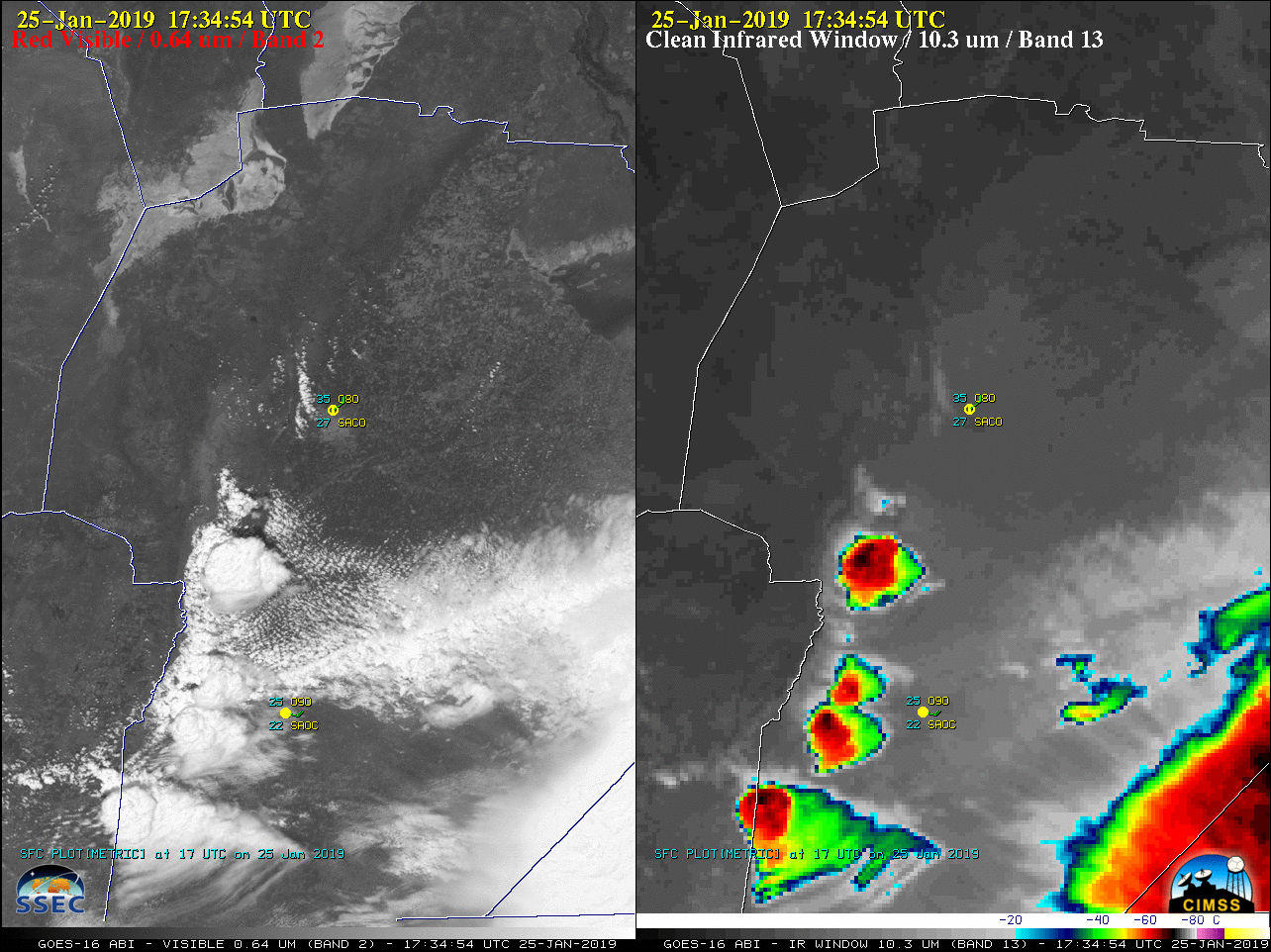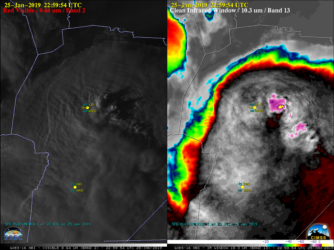
On 25 January 2019 a GOES-16 (GOES-East) Mesoscale Domain Sector was positioned over Argentina in support of the RELAMPAGO-CACTI field experiment, providing imagery at 1-minute intervals. “Red” Visible (0.64 µm) images (above) showed thunderstorms that developed and moved northward over the Córdoba (SACO) area — surface observations there (plot | list) showed a sharp... Read More
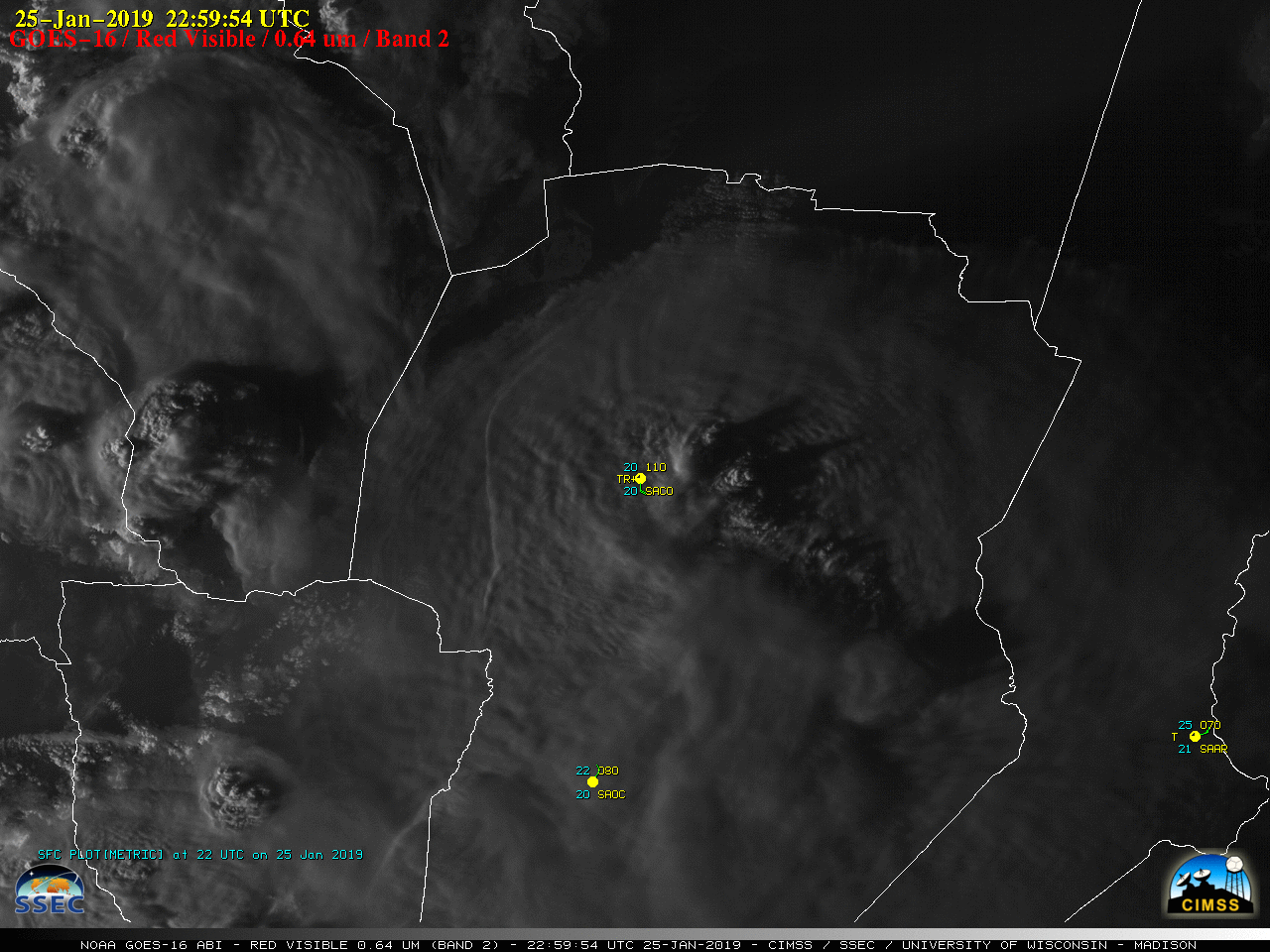
GOES-16 “Red” Visible (0.64 µm) images [click to play MP4 animation]
On 25 January 2019 a GOES-16
(GOES-East) Mesoscale Domain Sector was positioned over Argentina in support of the
RELAMPAGO-CACTI field experiment, providing imagery at 1-minute intervals. “Red” Visible (
0.64 µm) images
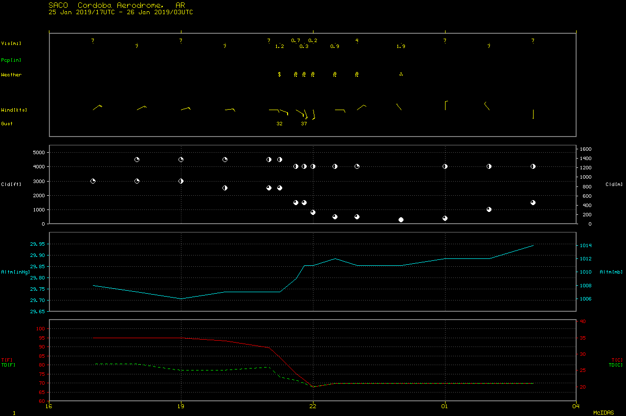
(above) showed thunderstorms that developed and moved northward over the Córdoba (SACO) area — surface observations there (
plot |
list) showed a sharp drop in temperatures along with wind gusts to 37 knots during the thunderstorm, which also produced hail and heavy rainfall. Two important features were revealed in the imagery: (1) an outflow boundary (from the decay of a large and long-lived Mesoscale Convective System to the southeast) which was moving slowly northward between between Rio Cuarto (SAOC) and Córdoba, likely helping to enhance boundary layer convergence and lift, and (2) a southward/southwestward flow of moist, unstable air — indicated by a plume of agitated cumulus clouds — approaching Córdoba. Toward the end of the day, the presence of an
Above-Anvil Cirrus Plume also became evident in the Visible imagery.
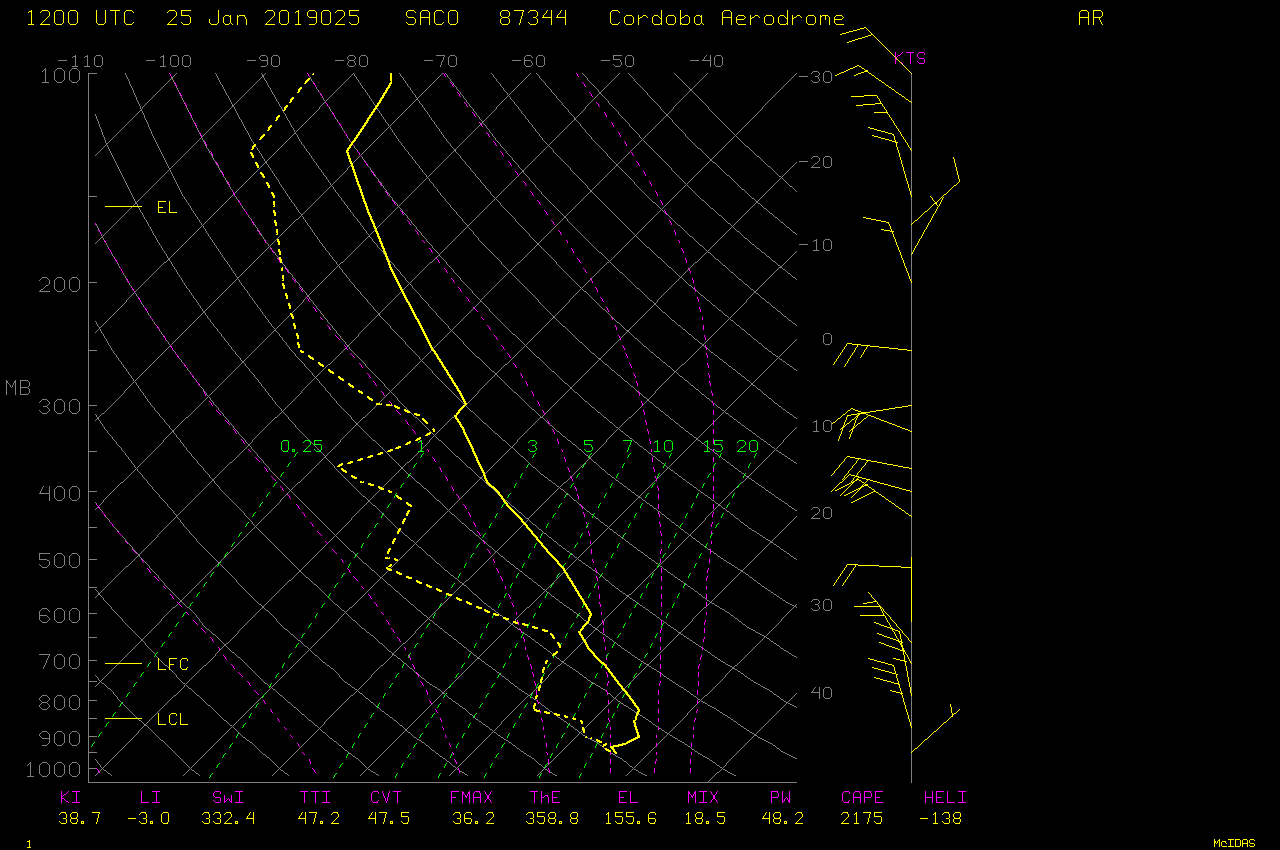
The corresponding GOES-16 “Clean” Infrared Window (10.3 µm) images (below) showed that infrared brightness temperatures of the pulsing thunderstorm overshooting tops were frequently -90ºC or colder (yellow pixels embedded within darker purple). This indicates a significant overshoot of the tropopause, which had an air temperature of -72.1ºC at an altitude of 15.2 km on 12 UTC rawinsonde data. Also note the development of a pronounced cold/warm thermal couplet over the core region of the storm, as an enhanced-V storm top signature formed.
![GOES-16 "Clean" Infrared Window (10.3 µm) images [click to play MP4 animation]](https://cimss.ssec.wisc.edu/satellite-blog/wp-content/uploads/sites/5/2019/01/G16_IR_ARGENTINA_25JAN2019_2019025_225954_GOES-16_0001PANEL.GIF)
GOES-16 “Clean” Infrared Window (10.3 µm) images [click to play MP4 animation]
A side-by-side comparison of GOES-16 Visible and Infrared images is displayed below.
![GOES-16 "Red" Visible (0.64 µm, left) and "Clean" Infrared Window (10.3 µm, right) images [click to play MP4 animation]](https://cimss.ssec.wisc.edu/satellite-blog/wp-content/uploads/sites/5/2019/01/G16_VIS_IR_ARGENTINA_25JAN2019_2019025_225954_GOES-16_0002PANELS.GIF)
GOES-16 “Red” Visible (0.64 µm, left) and “Clean” Infrared Window (10.3 µm, right) images [click to play MP4 animation]
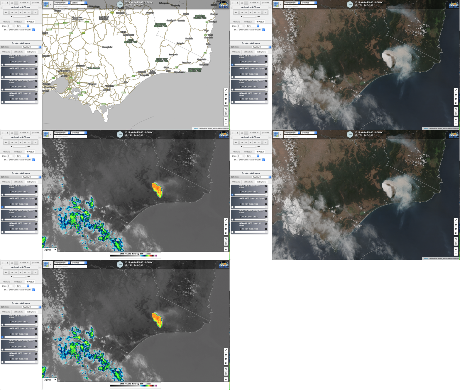
A toggle between NOAA-20 VIIRS True Color Red-Green-Blue (RGB) and Infrared Window (11.45 µm) images at 1734 UTC as viewed using
RealEarth (below) showed the early stage of convective development south of Córdoba, as well as the large decaying MCS to the southeast. Cloud-top infrared brightness temperatures with the developing storms were already -80–C and colder
(violet enhancement), about 10ºC colder than what was observed using lower-resolution
GOES-16 imagery at that same time.
![NOAA-20 VIIRS True Color Red-Green-Blue (RGB) and Infrared Window (11.45 µm) images [click to enlarge]](https://cimss.ssec.wisc.edu/satellite-blog/wp-content/uploads/sites/5/2019/01/190125_1734utc_noaa20_viirs_truecolor_infrared_Argentina_anim.gif)
NOAA-20 VIIRS True Color RGB and Infrared Window (11.45 µm) images at 1734 UTC [click to enlarge]
View only this post
Read Less


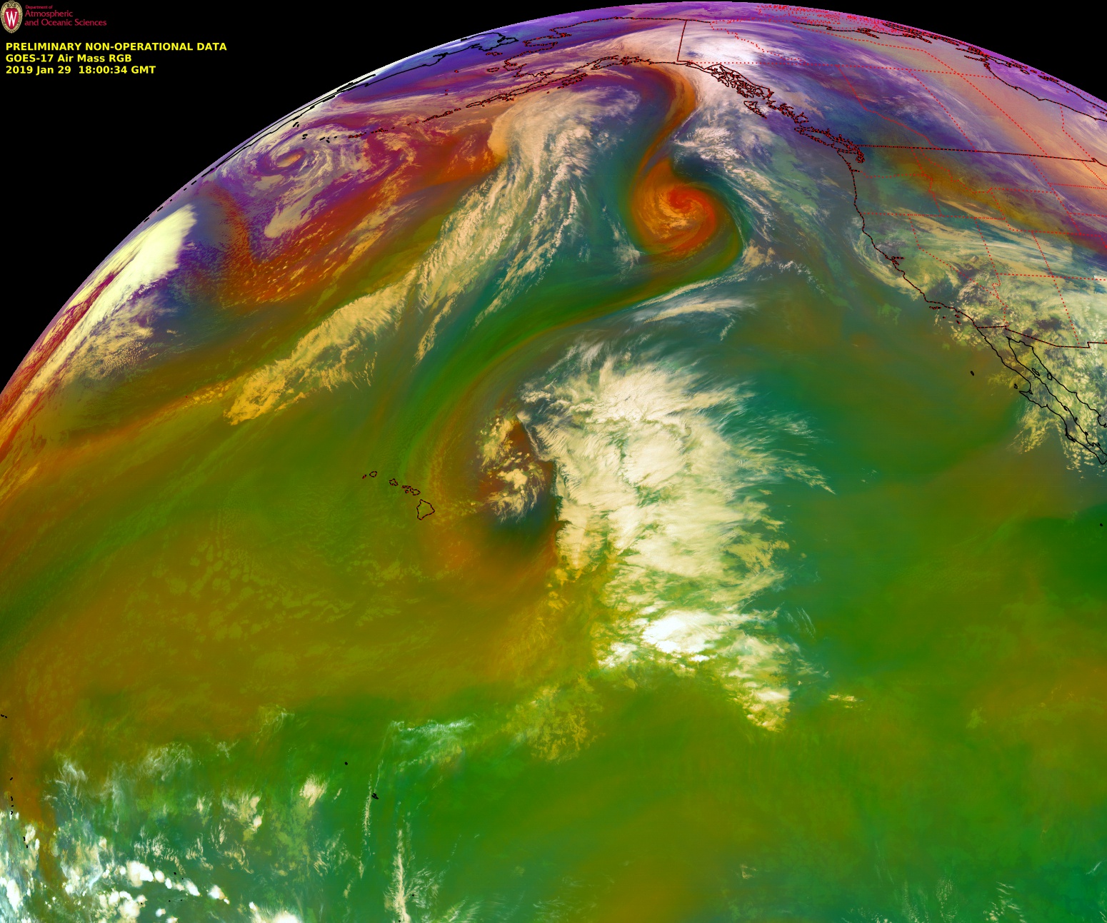
![GOES-17 Air Mass RGB images [click to play animation | MP4]](https://cimss.ssec.wisc.edu/satellite-blog/wp-content/uploads/sites/5/2019/01/190129_goes17_airmassRGB_anim.gif)
![GOES-17 Mid-level Water Vapor (6.9 µm) images, with and without contours of GFS75 model PV1.5 pressure [click to play animation | MP4]](https://cimss.ssec.wisc.edu/satellite-blog/wp-content/uploads/sites/5/2019/01/190129_goes17_waterVapor_pv1.5pressure_EPAC_anim.gif)

![Himawari-8 "Red" Visible (0.64 µm, left) and Shortwave Infrared (3.7 µm, right) images [click to play to animation | MP4]](https://cimss.ssec.wisc.edu/satellite-blog/wp-content/uploads/sites/5/2019/01/190125_himawari8_visible_shortwaveInfrared_Australia_pyrocb_anim.gif)
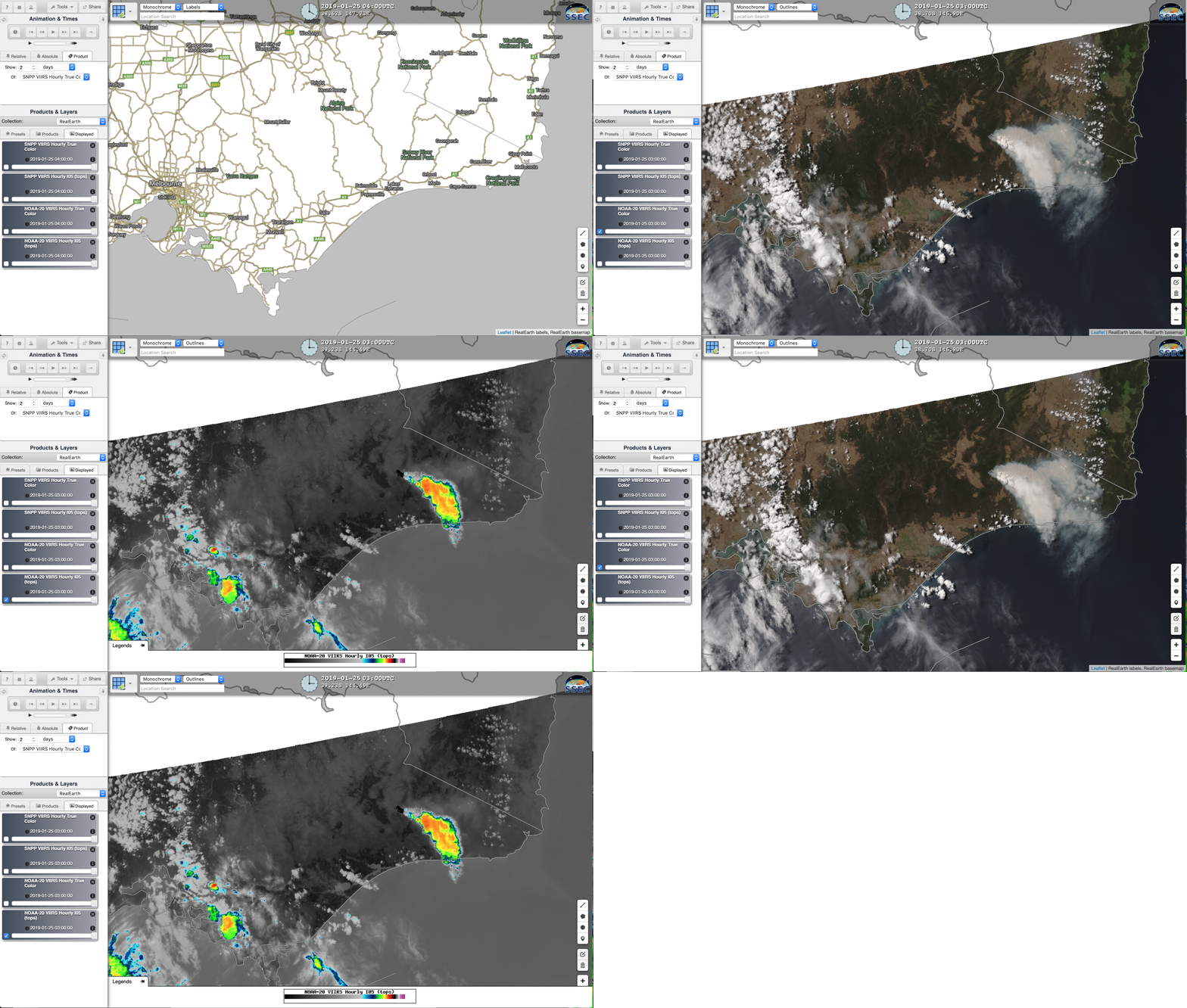
![VIIRS True Color RGB and Infrared Window (11.45 µm) images from Suomi NPP (0311 UTC) and NOAA-20 (0501 UTC) images [click to enlarge]](https://cimss.ssec.wisc.edu/satellite-blog/wp-content/uploads/sites/5/2019/01/190125_suomiNPP_noaa20_viirs_truecolor_infrared_Australia_pyroCb_anim.gif)

![GOES-16 "Red" Visible (0.64 µm) images, with hourly plots of surface wind barbs and weather type [click to play MP4 animation]](https://cimss.ssec.wisc.edu/satellite-blog/wp-content/uploads/sites/5/2019/01/G16_VIS_MIDWEST_BLSN_24JAN2019_2019024_180224_GOES-16_0001PANEL.GIF)
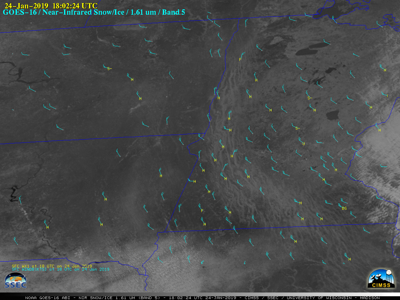
![GOES-16 Near-Infrared "Snow/Ice" (1.61 µm) images, with hourly plots of surface wind barbs and weather type [click to play MP4 animation]](https://cimss.ssec.wisc.edu/satellite-blog/wp-content/uploads/sites/5/2019/01/G16_SNOWICE_MIDWEST_BLSN_24JAN2019_2019024_180224_GOES-16_0001PANEL.GIF)
![GOES-16 Day Cloud Phase Distinction RGB images [click to play animation | MP4]](https://cimss.ssec.wisc.edu/satellite-blog/wp-content/uploads/sites/5/2019/01/190124_goes16_dayCloudPhaseRGB_Upper_Midwest_anim.gif)