This is a working page/manual which describes the set-up and operation of our Trimble/UNAVCO GPS unit on Andros Island during CAMEX3.
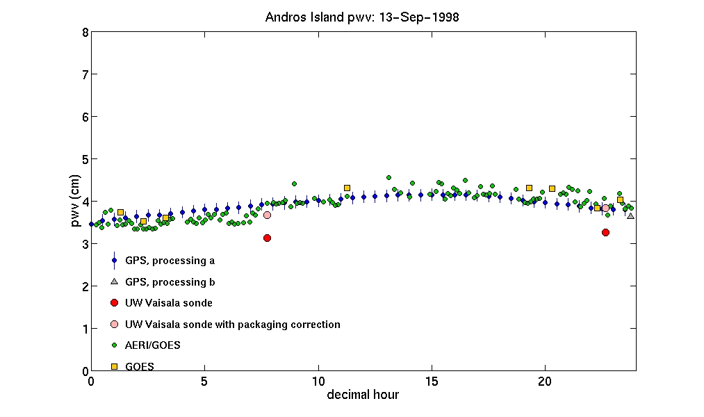
GPS derived precipitable water vapor:
This analysis of RINEX files and conversion to pwv values provided by Teresa Van Hove of UNAVCO.
data files
plots
ASCII files of :
- UW Vaisala sonde pwv with and without Vaisala corrections
- AERI/GOES surface T&P, pwv, and integrated mean temperature
- GOES surface T&P, pwv, and integrated mean temperature
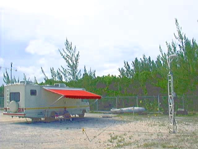
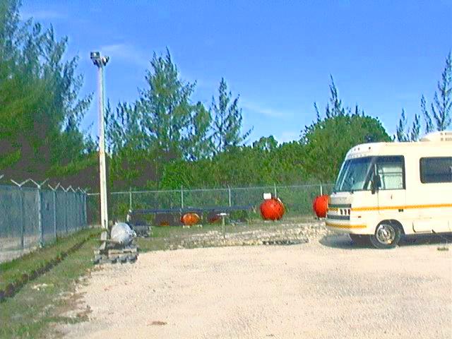

pictures c/o John Short
Outline
Set Up
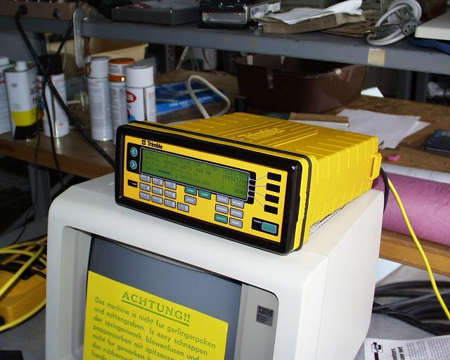
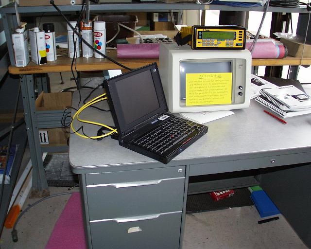
- Required Equipment (click for pictures)
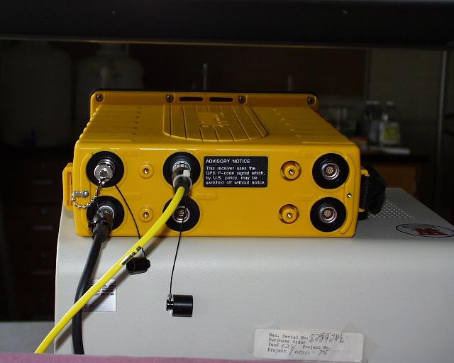
- Reciever. Trimble 4000SSi, PN 24840-42, SN 3828A23658. rear view.
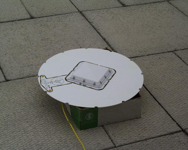
- Antenna. Trimble "Compact L1/L2 with groundplane", PN 22020-00, SN 0220122324
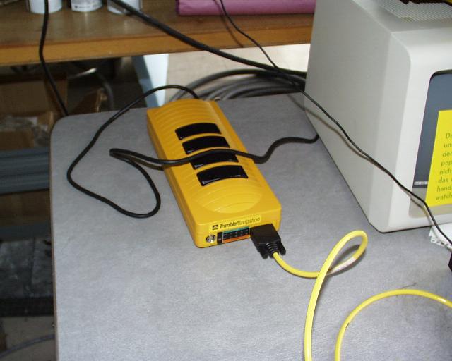
- Office Support Module 2 (OSM2). model no. 20669-40, SN 0220126902, and AC power cord.
- Antenna mount. built on 5th floor.
- Antenna Cable. longest cable with with coax (antenna end) and LEMO (reciever end) connectors. label: 14553-00 Rev D1 DCA 9814
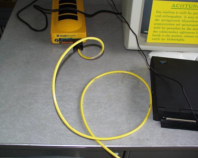
- Serial port cable. with male and female 9 pin connectors. label: 14284 Rev A1 DCA 9819.
- Laptop computer. this is Bob's IBM Thinkpad with Window's hard-drive installed. Has the up/downloading GPS software "GPLoad v2.42" installed on it and has been (or will be) configured for using its ethernet card.
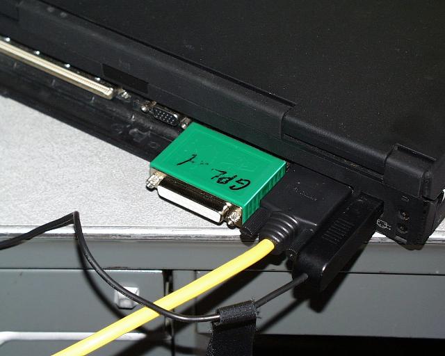
- Dongle. This thing is called a Dongle, which is Australian for "computer security key" ;-) .
- Other Equipment
- Useful: Manuals, DAT2RIN documentation
- Haven't used these yet: other software, field note pads, other cables, battery packs, etc...
- Antenna:
- Position the antenna
Screw the antenna into the antenna mount. Position it away from the AERIbago and any other large structures. The idea is to give the antenna a clear sky view in all directions. Rotate the mount so the arrow on the antenna ground plane is pointing North. Depending on the surface, use the guy wires to secure the mount. Make the position of the antenna as stable as possible. Also, level the antenna so that the ground plane is horizontal. - Record the uncorrected height of the antenna
Refer to pages 187 to 189 and pages 168 to 170 of the Application Guide manual on how to measure the uncorrected height of the antenna. The reciever will ask for this when starting a data collection session. Email message on uncorrected antenna height.
- Position the antenna
- Reciever, OSM2, and computer
- Attach antenna cable
Attach coax end of antenna cable to antenna. Attach other end of antenna cable (the LEMO connector) to the reciever. The reciever accepts the antenna cable in the the connector labeled ... you guessed it ... "antenna". If the LEMO connector is in correctly, you can't pull the cable out without releasing the LEMO sleave. - Attach OSM2 to reciever
Attach the LEMO style cable coming out of the OSM2 to the reciever using the "PWR-I/O 1" connector on the back of the reciever. This serves as the power supply and data cable for the reciever. - Plug in the OSM2
Supply power to the OSM2 by attaching the black AC power cord to the OSMA and to an appropriate power outlet on the AERIbago. The red light on the front of the OSM2 should light up. - Attach data cable to OSM2 and computer
Attach the 9 pin serial port cable to the front of the OSM2 and to the serial port of the laptop. - Attach Dongle to computer
Attach the green Dongle to the parallel port of the laptop. This allows you to run "dat2rin".
- Attach antenna cable
Operations
The GPS signals will be collected by the reciever
using a "pre-planned static survey" that has already been
downloaded to the reciever at UW. This shouldn't mean
anything to you unless you've read the mauals. What it means is
that you have only a few things you have to do to the reciever to
get it to start working the way we want it to. After going through
these steps, the reciever will start taking data from the antenna
and producing data files, one for every day. At the end of each
UTC day, the reciever will continue to take data from the antenna
and begin writing a new data file. Without interference, this
type of operation should continue throught the experiemnt.
The only thing that needs to be done then is to
a) periodically (every 4 or 5 days or so) download the data files
from the reciever,
b) run dat2rin on those files (optional), and
c) ftp the files back to UW.
- Collecting data
- Turn on the reciever by pressing the green POWER button.
- Start the Pre-planned Survey: bago-cmx-3
- The screen will display several choices for taking data. Using the
softkeys on the RHS, select START PRE-PLANNED (SINGLE SURVEY).
- The screen should then display SELECT STATION: bago. Press
ACCEPT.
- The screen should then display SELECT SESSION: cmx-3.
Press ACCEPT.
- The reciever will beep and display WARNING: THE SESSION YOU HAVE SELECTED IS AN EVERYDAY SESSION. Press Auto Survey Timer.
- It will then display AUTO SURVEY MODE IS OFF. Press ENABLE.
- Then select ENABLE AND STAY AWAKE.
- The screen should then ask for info on the antenna.
- Use the keypad numbers to enter the previously measured uncorrected antenna height. (Press the Units softkey to change the input units if desired.) Press ENTER when done.
- Use the number keypad to enter the antenna serial number: 0220122324 - don't worry that all the numbers don't fit.
- Press accept.
- The screen will display STARTING SESSION : bago-cmx-3 IN 30
SECONDS and the data collecting will begin.
- After data collection begins, press LOG DATA, then CHANGES, and then ANTENNA HEIGHT. Make sure the uncorrected antenna height is correct, leave the measurement type as uncorrected, select Compact L1/L2 W/ GRND P as the antenna type, if not already selected, and correct the antenna serial number if needed. Press Accept.
What have you just done ?
You have set various parameters for the data collection:
- collect data in "any Day at Specified Time" static suvey mode
- begin data collection at 0:02 UTC everyday
- collect data for 23:59 hours and then start another identical session.
- minimum elevation angle: 7 degrees
- minimum number of satellites: 1
- delay logging interval: 30 seconds
- record position every 5 minutes
- store the data in data files called "bagocmx-3"
- The screen will display several choices for taking data. Using the
softkeys on the RHS, select START PRE-PLANNED (SINGLE SURVEY).
If there is a power outage or other reason for the reciever/antenna to stop taking data, simply follow the instructions in Collecting Data again. If starting after a power failure, also refer to page 203 of the Applications Guide manual.
- Renaming and downloading reciever data files
- Start GPLoad on the laptop by double clicking on the GPLoad icon.
- In the GPLoad window, set Device to GPS reciever, Port to COM1, and press Connect.
- Select the Data type to be Raw Obs and the data files on the reciever will be listed in the Available Files panel.
- Select the file to be downloaded. i.e.
bago-cmx-3 7/29/98 00:01:00.
(FYI: the file is created one minute before data collection begins.) - Press Rename and rename the file to "bago" plus the
julian day for the file creation date. i.e. bago210.
In the case of a power failure or other reason to stop data collection and two or more data files are created for the same julian day, assign distinct file names. i.e. bago210a, bago210b, etc. - Set the destination directory to C;\GPLoad\Data
- Re-select the file in the Available files panel, press Add, and then Transfer to download the renamed file. The file will only have a different name on the laptop.
- This download process gets an .r00 file from the reciever, converts it into readbale format and put the output into four sepate files in the Data directory. See the Data section for a description of the files.
- Repeat for other files.
- Don't try to download the file currently being written to. GPLoad will allow you to try this, but the reciever won't.
- To quit, press Disconnect and then Close.
- Running dat2rin
This step is not required. Running dat2rin on the reciever .dat files converts them to RINEX format (a universal reciever ascii format). Since we have dat2rin on a computer (rainbow) at SSEC, we can do this conversion at SSEC.- Open an MS-DOS prompt window on the laptop, cd to C:\GPLoad, and insert the Dongle into the laptop's parallel port.
- To run the program, enter, for example
dat2rin -rrunner -oobserver -Assec -aG0 Data/file.dat where runner is the name of the person running dat2rin, observer is the person who made the gps observations, ssec is the name of the organization, and G0 is the code for our particular reciever. - This will produce a RINEX format observation (file.YYo) and navigation (file.YYn) files in Data/.
- More info on running dat2rin is avaliable in C:\GPLoad\Dat2rin.wri.
- Running RINMERGE
If you have more than one set of files for a given day, you can combine the RINEX files into one file using RINMERGE. Rinmerge is a program that came with dat2rin. To combine two observation files for the same day, type i.e.
rinmerge ba98218a.98o+ba98218b.98o ba98218.98o
More info on running rinmerge is given in the dat2rin documentation.
- Sending files back to UW
ftp the files to tyler.ssec.wisc.edu and put them in /home2/davet/GPS/Data/.Click here for the new and improved Dummy's guide to GPS Data File Handling Procedures During CAMEX-III
Data
- Data directory on tyler.ssec.wisc.edu
This directory contains the data files downloaded from the reciever using the PC software "GPLoad". For each reciever file, GPLoad automatically converts the *.r00 files into a data file (*.dat), an ephemeris file (*.eph), an ionosspheric data file (*.ion), and a measurement summary file (*.mes), all with the same base filename. The base directory and filenames are "BAGOxxx", where xxx is the julian day of the observations. If dat2rin has been run on a particular .dat file, there will also be two RINEX format files: the observation file (BAGOxxx.98O) and navigation file (BAGOxxx.98N). If more than one reciver data file per day was created, rinmerge may have been used to combine the resulting RINEX files (i.e. BAGO218a.98O and BAGO218b.98O combined into BAGO218.98O).
- archived AUTEC met data :
ASCII
format |
HTML
format
These directories contain data from the AUTEC met station. More info on the met station.
The format of the ASCII format files is:- column 1: decimal julian day
- column 2: observed pressure (mbar)
- column 3: corrected pressure (mbar). to account for met station (10 masl) / antenna (~5 masl) height difference using dp/dz of 110 mbar/km.
- column 4: observed temperature (C)
- column 5: observed relative humidity
- Near surface and integrated mean temperatures from AERI/GOES retrievals
Useful Links
- Trimble:main page | GPS | Land Survey | 24 hour Support | TIPs | 4000SSi
- UCAR: Realtime pwv | GPSMET | GPSMET article | SuomiNet | UNAVCO | UNAVCO equipment support
- NOAA : GRDL antenna calibration: Trimble 22020-00 | GRDL GPS | ERL GPS | CORS | NGS | FSL GPS-IPW
- Andros Island AUTEC: main page | weather | archived AUTEC met data on arm1 : html format | archived AUTEC met data on arm1 : ascii format
- GAMIT
- GPS info: U Texas 1 | U Texas 2 | UTexas 3
- RINEX : paper
- CAMEX3 links
Contact Info
Pager: (800) 800-9856 (Mon.-Fri., 6am - 6pm MDT)
Telephone: (303) 497-8016 (Mon.-Fri., 9am-5pm MDT)